Wire harness in a car in NX

Wire harness

Wiring harness design

Take advantage of fully integrated 3D wiring harness design software that allows you to design and route harnesses in complex assemblies. The capabilities of NX Routing Harness enable you to produce a wire harness directly from NX CAD product assembly models.

White paper

Integrated electromechanical wire harness design

Read how to maximize efficiency and produce high-quality products with short timelines by integrating ECAD and MCAD for wire harness design.

A person on a computer with a digital overlay of a bulldozer

Create fabrication models and drawings

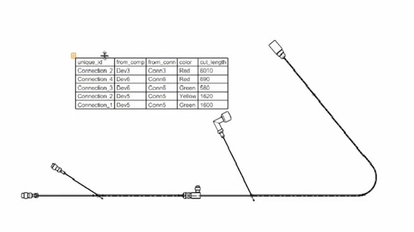
Reduce production time as NX readily creates information for harness manufacturing. Automatically create a flattened model of the wire harness that includes the electrical intelligence and details such as tie wraps, clips and grommets, and relative positions of connectors.

Manufacturers can use the flattened model as a reference for 3D jig design. Or, you can use NX to easily create accurate formboard drawings.

NX Electrical Routing formboard output for manufacturing.

Reuse logical design data

Leverage NX wire routing and harness design as it uses the connection and component information from the logical design schematic. You can quickly import netlists of wire connection data from ECAD systems. Or, use a wizard-style interface to create and modify connections.

NX Routing Electrical Ports and Logical connection.

Connection/component-driven wire harness design process

Leverage auto-selection in NX CAD. Using the imported ECAD component information, NX can auto select the correct part from the routing library for placement.  Correct placement between components is ensured by preconfigured routing ports which control engagement and rotation.  Create robust spline paths between connectors and other components like clamps. Splines are associative and can be set to avoid minimum radius kinking.  Once all connectors are linked with paths, NX will route the wires automatically along this network and create bundle solids with the correct volume and mass. This connection list with the updated wire lengths can also be sent to ECAD for further analysis.  
 
With parametric wiring models, you can more easily manage design changes, analyze clearances and interferences and accurately calculate wire lengths and bundle diameters.  

Built-in design rules check and enforce standard practices and ensure connectivity to reduce production costs and assembly defects. To quickly identify and correct violations, you can check rules during design or on demand. 

A failed electrical routing bend analysis check with visual tag and failure information window in NX.

Mechanical-electrical design

Integrate mechanical and electrical workflows using NX and Capital to enable seamless collaboration and data exchange between design teams, reduce errors from manual data transfers and accelerate product development by allowing early detection and resolution of design challenges.

Streamline your workflow with Capital X Panel Designer

Simplify the traditionally manual process of cable routing and wire length updates by connecting NX (mechanical CAD) with Capital X Panel Designer (cloud-native electrical CAD). Integrating your mechanical and electrical design workflows has never been easier within Capital.