A man is looking at the Simcenter electronics cooling CFD and multiphysics software tool on a screen.

Simcenter

Electronics cooling simulation

CFD thermal analysis to ensure electronics performance and reliability

Optimize thermal management of electronics

Simcenter has a wide range of accurate electronics cooling computational fluid dynamics (CFD) and multiphysics software tools to address any application, and enable engineers of different skills and experience. Combined with electronic design automation (EDA) and CAD workflow connectivity and precise thermal measurement, Simcenter accelerates your thermal design process.

Electronics cooling simulation capabilities

Chip and IC package thermal simulation

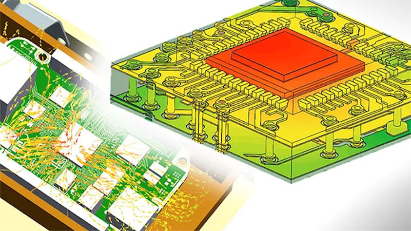
For semiconductor OEMs it is crucial to understand package structure influence on thermal behavior reliability, especially with increasing power density and complexity in modern package development. Challenges such as those in complex system-on-a-chip (SoC) and 3D-IC (integrated circuit) development mean thermal design must be integral to package development. An ability to support the onward supply chain with thermal models and modeling advice that goes beyond datasheet values is of differentiated value in the market.

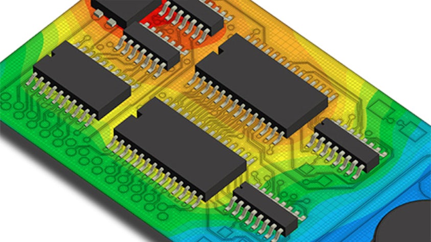
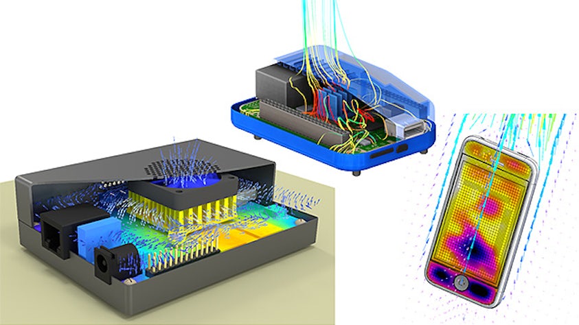
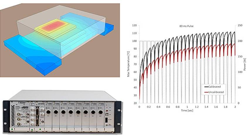
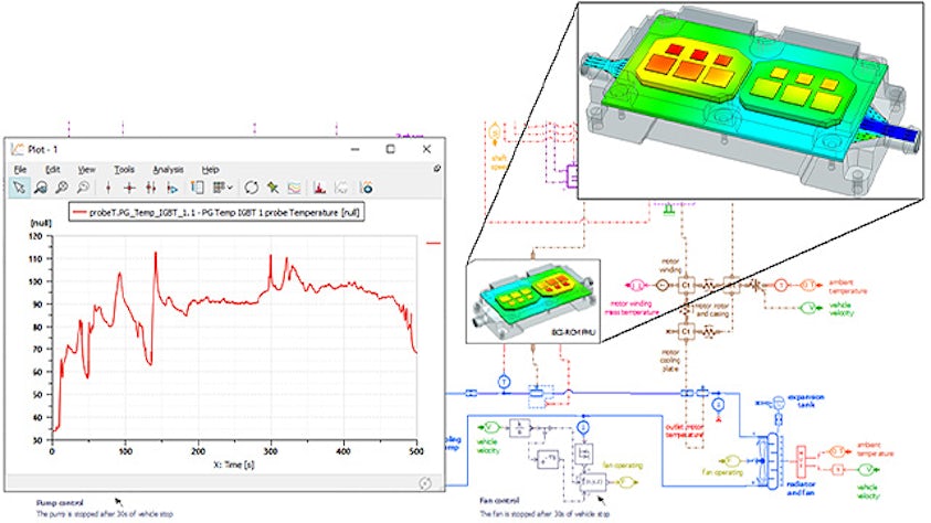
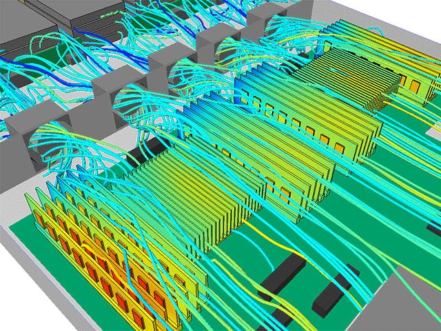
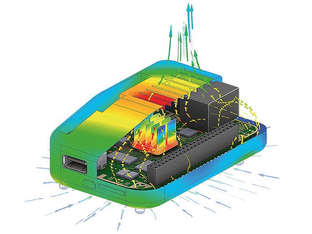
For electronics manufacturers integrating packaged ICs into products, it is important to be able to predict with accuracy the junction temperature of a component on a printed circuit board (PCB) within a system-level environment to develop appropriate thermal management designs that are cost effective. Electronics cooling simulation software tools provide that insight. It is desirable for thermal engineers to have options available for modeling fidelity of IC packages to suit different design stages and availability of information. For highest accuracy modeling of critical components in transient scenarios, a thermal model calibrated with junction temperature transient measurement data.

Explore package thermal simulation

PCB thermal analysis

Model the thermal performance of complex multi-layer PCBs and mounted devices to accurately predict component junction temperature. Understanding board thermal influence requires the right level of accuracy, suited to the available information at each stage of development.

Within electronics thermal design, options for PCB thermal modeling fidelity from simple types, thermal conductivity in each layer, to explicit modeling of copper trace are suited to different stages of development. This includes from exploring component placement to verifying the thermal performance of a fully routed board. Among the latest approaches to PCB thermal analysis is to model an entire board as network assembly which is computationally efficient without sacrificing accuracy.

Electronic design workflow connectivity and the ability to import board information from leading EDA software file formats and also update models with new information, is a key enabler for efficient thermal analysis processes. There are clear advantages in tools that allow engineers to easily process ECAD file data containing board layout, routing details and component information to speed up thermal model creation alongside methods to implement power information in thermal analysis.

Watch the webinar - multi-layer PCB thermal and thermo-mechanical simulation

Thermal representation of a complex multi-layer PCB showing its temperature

PCB electro-thermal co-simulation

To achieve highest accuracy in PCB thermal analysis, including joule heating of the copper trace on the PCB, it is advantageous to collaborate with electronic engineers working on PCB signal and power integrity simulation. Co-simulation between 3D electronics cooling software and EDA power integrity simulation software accurately represents board copper-trace power dissipation accounting for electrical resistance changes with temperature. Explore reasons for PCB electrothermal co-simulation in this video.

Enclosure thermal management

Electronics enclosures must house PCB assemblies, components, power supplies, connectors, sensors and much more. It must also provide sufficient cooling airflow or conductive heat transfer to the ambient surroundings to ensure reliable product performance. Whether you are designing a forced convection cooled industrial enclosure, a sealed avionics enclosure or the latest thin form factor consumer electronics product, these 3D CFD thermal analysis tools allow for rapid exploration of different cooling solutions. Tools that can handle MCAD geometry easily or directly for CFD simulation are advantageous so that you focus less on pre-processing steps and more on enclosure system-level thermal modeling results and optimizing your design.

Download the complete guide to enclosure thermal management for design tips.

An electronics cooling simulation and thermal streamlines visual from the Simcenter software.

Datacenter cooling and large system thermal modeling

Datacenter cooling for reliable operation is crucial to avoid outages. Datacenter cooling worldwide is a significant proportion of energy usage beside considering individual site operating costs, so efficient cooling design is of high importance for successful and sustainable operation. Using CFD simulation, you can predict the airflow and heat transfer in datacenters and similar large complex systems. You can ensure servers, racks and critical components stay within required temperature limits, and develop the most efficient cooling strategy.

Read the whitepaper on 11 key tips for efficient datacenter cooling now.

Visualization of a datacenter and a heatmaping of the airflow

Liquid cooling

Liquid cooling offers advantages for effective and efficient cooling of electronics applications where there are high heat dissipation requirements for operation and reliability purposes. From minimizing custom cold plate pressure drop in power electronics applications to aiding thermal design in the area of increasing adoption of immersion cooling of servers, use accurate 3D CFD electronics cooling simulation and 1D fluid dynamics to optimize your liquid cooled design.

Watch the video (right) on edge server liquid cooling advantages insight from Iceotope Technologies.

View on-demand presentation - AI hardware thermal management: Deep learning machine liquid cooling insights from Electronic Cooling Solutions Inc

Combining thermal test, simulation and model calibration

Enhanced thermal analysis accuracy helps meet increasingly demanding design requirements in modern electronics development. Calibrating a thermal model with transient thermal measurement data can help you to achieve the highest accuracy in thermal simulation. Automatic thermal model calibration overcomes the need for prohibitively time-consuming manual calibration steps of making incremental changes to thermal model attributes. Using a calibrated thermal model means that risks of under-design can be addressed to ensure reliability through accurate modeling of mission profile scenarios to verify performance. At the same time, with higher confidence in accuracy, engineers can address potential areas of over-design to reduce product costs.

For an overview of thermal transient test methods and simulation model calibration
watch the on-demand presentation: Semiconductor package thermal characterization – thermal metrics, reliability to quality

An image of a Simcenter electronics cooling CFD and multi-physics software tools addressing applications enabling engineers of different skills and experience.

Boundary condition independent reduced order models (BCI-ROMs)

Boundary condition independent reduced order model (BCI-ROM) technology offers advantages for fast transient thermal analysis of electronics orders of magnitude faster than full 3D CFD while preserving accuracy. A BCI-ROM is automatically generated from a 3D conduction analysis which maintains predictive accuracy but can solve 40,000+ times faster in demonstrated cases. The “boundary condition independent” aspect of reduced order models is extremely valuable, as they can be used in any thermal environment. BCI-ROMs can be generated in different formats to support standalone fast solving in matrix format, incorporated into circuit simulation for electrothermal analysis tools (VHDL-AMS format) or used in 1D system simulation tool modeling (FMU format).

View the blog: The future of thermal design – earlier electrothermal analysis

Watch the on-demand: Accelerate electronic systems design with thermally aware electrical simulation (Featuring insight from a ROHM Semiconductor guest speaker)

The Boundary Condition Independent Reduced Order Model (BCI-ROM) visual from the Simcenter software.

Accelerated thermal and thermo-mechanical analysis workflow

Thermal design for reliability of electronics products benefits from accurate prediction of temperatures, gradients and cyclical transient variations which can be subsequently used in thermo-mechanical stress analysis. Thermo-mechanical analysis is used to investigate modes of failure, potential areas of degradation risk, to durability and lifetime insights.

CFD to finite element analysis (FEA) thermo-mechanical stress evaluation workflows can take several forms. CFD analysis can be performed by a dedicated thermal analyst in an electronic cooling software and 3D transient temperature results can be exported to a mechanical FEA tool. Alternatively, engineers working in the CAD environment may benefit from a combined CAD-embedded thermal CFD and thermo-mechanical stress analysis to shorten overall analysis time.

Explore three workflows for CFD electronics cooling simulation and FEA electronics thermo-mechanical stress analysis in this on-demand webinar.

A visual of the thermal design for reliability of electronics products from the Simcenter software.